System Details
High Level Overview
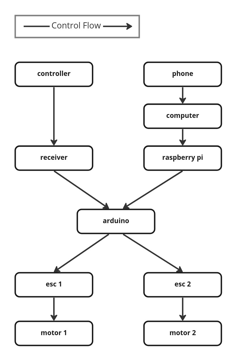
Our system consists of a CyberKAT, a kit robot from Spyker Workshop, a Raspberry Pi, an Arduino Uno, an iOS device, and a laptop with ROS2 Foxy installed. By default, CyberKAT is operated with a remote control communicating with a receiver on the robot, which then signals two electronic speed controllers (ESCs) through the onboard PCB to change the motor speeds. We wired in an Arduino Uno between the receiver and ESCs, allowing manual joystick control to still be available, and connected a Pi to the Arduino so that they can communicate over Serial. The iOS device communicates wirelessly with the computer to send live odometry data and video feed, which the computer processes and uses to command the Pi.
Software Systems
Swift Interface
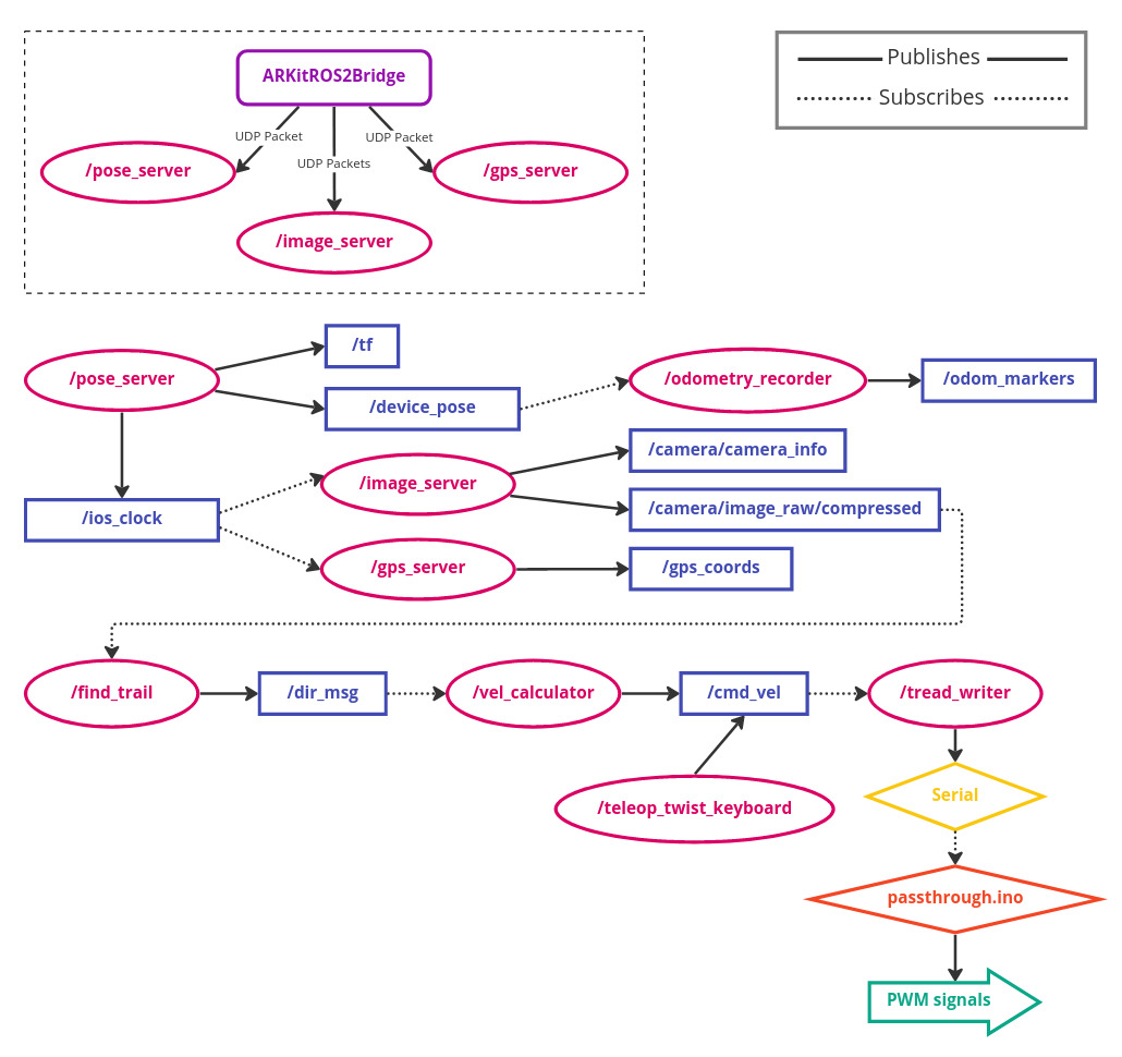
The ARKitROS2Bridge app is programmed in Swift using SwiftUI for the interface and ARKit for the backend. The interface allows the user to see the live camera stream, input the IP address for wireless connection between the phone and computer, and start and stop the data stream. The app pulls the camera pose data (4x4 transform containing position and orientation) and the camera frames from ARKit, and pulls the phone’s GPS coordinates from the CoreLocation library. The app then broadcasts each of these as UDP packets to different ports on the given IP. Due to the size of each camera frame, they are split into multiple packets prior to being broadcast.
Machine Learning
Our machine learning algorithm is designed using this paper. We trained our model using the dataset collected by the paper's author's as well. The model architecture is a DNN classifyer that takes in images from our camera feed and classifies the location of the as one of three categories - left, right, or center. Then, using the output weights for each category, we calculate the linear and angular velocity that the robot should travel at. Due to time contraints, the model that we are using in our demo videos is only trained on a tenth of the data using 10 epochs, which results in a much less reliable model. One issue that we ran into when into when testing our system was that the model is most likely to predict a trail as leadin to the right, which means that our vehicle then frequently turns to the right when it shouldn't.
ROS Architecture
The overall ROS architecture is summarized in the system diagram at the top of the page. Each type of UDP packet sent by the ARKitROS2BRidge app is received by a different ROS node functioning as a server. These nodes are pose_server, image_server, and gps_server. The pose data is converted to ROS coordinate frame and published as a PoseStamped to the topic /device_pose. The camera images are stitched back together and published as a CompressedImage to topic /camera/image_raw/compressed. The GPS data is published as a custom message type called CoordinateStamped to the topic /gps_coords.
The odometry_recorder node subscribes to the /device_pose topic to place markers in RViz at the current location of the device as well as generate a CSV with the robot path. find_trail is the node that runs our trail detection ML model. It subscribes to /camera/image_raw/compressed, runs each camera frame through the model, retrieves weights for whether to classify the image as left, right, or center of a trail, and publishes a message of custom type Direction to /dir_msg. This is read by the vel_calculator node, which contains the controls logic for the robot and determines a linear and angular velocity to publish as type Twist to /cmd_vel. The node tread_writer runs on the Pi and subscribes to /cmd_vel, then sends an appropriate message over Serial to the Arduino.
Arduino Control
The Arduino functioned as a finite state machine with three different states: passive, remote control, and serial control. The body loop of the arduino code would begin by checking which state it should be in, determined by the position of the left stick on the remote control. Different positions would send different PWM frequencies to the remote control receiver, which would send those frequencies to one of the Arduino's digital input pins. The beginning of the arduino's loop would determine that input frequency, and set the state accordingly.
The first state was "passive". The arduino would enter this state if the left stick was down, or the controller was off. Passive mode actively wrote speeds of 0 to the treads, meaning that no matter what input was going into the arduino from anywhere else, TrakBot wouldn't move. This was useful for both safety and testing. It meant TrakBot wouldn't move when we didn't expect it to, important given its size, noise, and speed, and functioned as an emergency stop. This came in handy when the loss of a gear and resulting loss of control caused TrakBot to almost run into one of our instructors.
The second state was "remote control". The arduino would enter this state if the left stick was in the middle of its range. Remote control mode meant the Arduino would listen to the PWM frequencies sent in by the remote control's right stick (the one used for driving TrakBot before our modifications), and drive Trakbot accordingly. This was useful for getting TrakBot into position for testing, as teleop control was difficult to do precisely. This also functioned as a useful troubleshooting method. We had enough interconnected systems that any number of things could go wrong, so switching TrakBot to remote control mode let us identify if the error was at/below the Arduino level (e.g. esc's not on, no power to arduino, etc) or above (e.g. serial communication error). This mode functioned entirely separately from anything higher in the systems stack.
The third and final state was "serial control". The arduino would enter this state if the left stick was at the top of its range. Serial control mode meant the Arduino would listen to input over the serial port in the form of "[linear velocity],[angular velocity]" with start and end markers. This mode was how the raspberry pi would communicate with the Arduino, and therefore how our entire system would activate the treads and make TrakBot move. When the Arduino entered this mode, it would activate an LED to make its status visibly obvious to an observer.
Once the mode was selected, the arduino would parse the input (for serial and remote control) to get the desired linear and angular speeds. It would then calculate the speeds each tread must spin at to achieve that speed, and calculate the appropriate PWM signal to send to each ESC to achieve that speed. Finally, it would write those speeds and TrakBot would move!
Mechanical and Electrical Hardware Systems
Hardware System Overview
Our hardware system consists of a remote control and receiver, a phone, a computer, a Raspberry Pi, an Arduino, two electronic speed controllers (ESCs), and two motors driving the robot's tank treads. The phone and computer communicate wirelessly over IP, the computer and Pi communicate via ROS, and the Pi and Arduino communicate over Serial. The Arduino, receiver, ESCs, and motors are connected electrically.
Raspberry Pi Configuration
The raspberry pi 4 we used for this project is running ubuntu server 20.04. It is normally running in a command line only or “headless” state to save computational resources but can be run with a gnome desktop interface if desired. The Pi is configured with a static ethernet IP to make sshing into the system easy. From there we are able to initialize our own access point known as the “TrakBot” network. Once this network is created, we are able to wirelessly run our ROS2 system on both the pi and a student laptop.
Camera Hardware
Because our machine learning database was a set of images taken at the full height of an adult we wanted to get our camera to a higher elevation to give us the best chance of success. Because our camera is an iphone we are able to use any array of phone mounts for this system. We created a wooden platform with several locating points for the phone mount then used a combination of painters tape and hot glue to secure it to the robot without permanently damaging it. Unfortunately, when we tested the robot in sub freezing temperatures and the robot experienced a large force tilting back, the hot glue failed and the phone mount fell. Fortunately, the robot and computational hardware was undamaged.
Mechanical Challenges
Our TrakBot faced a few mechanical problems while field testing. Our biggest issue was the left main drive gear. The shaft on the motor was not slotted perfectly flat which resulted in the set screw of the gear actually pushing it off rather than retaining the gear on the shaft. We were able to minimize this issue by using loctite on the shaft to act as an adhesive agent. This did not solve the problem but it allowed us to test for longer durations without having to stop and reset the gear.
Another mechanical issue we ran into was losing one of the treads on the robot. While driving in grass, a tread completely detached from the drive assembly. This is a common flaw in treaded vehicles and often is a result of a lack of proper tension on the tread. We were able to reinstall the tread and increase the tension on both sides resulting in a more secure and slightly more quiet robot.

